Power Factor Correction
What is Reactive Power ?
The rational use of electrical energy calls for economical generation, transmission and distribution with little loss. That means restricting all factors in electrical networks that cause losses. One of these factors is lagging reactive power. Consumers in industrial and public electrical networks are primarily of an ohmic-inductive nature.

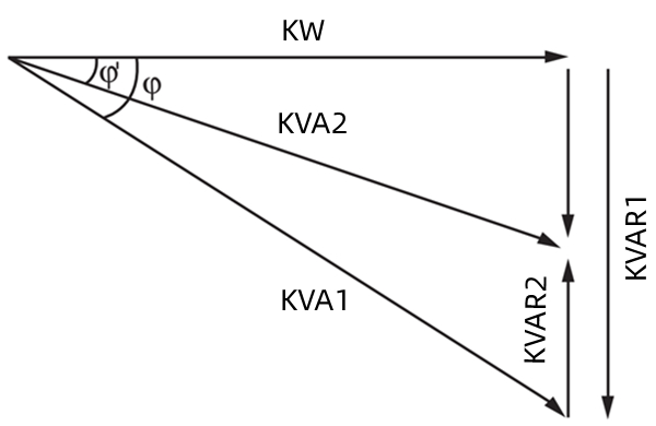
KW:power consumed by system
KVA1:apparent power
KVA2:apparent power after correction magnetising KVAR1
KVAR2:capacitor Kvar
Cos1:power factor before
Cos2:power factor after
What is Power Factor Correction (PFC)?
The purpose of systems for power factor correction in networks is to compensate the generated lagging reactive power by leading reactive power at defined nodes. In this way impermissibly high voltage drops and additional ohmic losses are also avoided. The necessary leading power is produced by capacitors parallel to the supply network, as close as possible to the inductive consumer .
What is Power Factor Correction System?
Power factor Correction system are including Static capacitive compensation devices and automatic capacitive compensation devices. Static capacitive compensation devices reduce the lagging reactive power component transmitted over the network. If network conditions alter , the required leading reactive power can be matched in steps by adding and taking out single power capacitors (regulated PFC) to compensate the lagging reactive power.
A transfer of high power with minimum losses is a problem in electrical engineering. To go from low to medium or high voltage only partly solves the problem, as one of the most important factors, cos¢, must not be neglected.
Due to the widespread use of induction motors in trade and industries, the power factor in power facilities has increasingly deteriorated and impairs an optimum utilization of installed facilities.
With the power factor getting worse (i.e. with the reactive current increasing) the voltage drop increases, which makes voltage control more difficult and negatively affects power values with the users, due to under-voltage.
To achieve the most suitable power factor, there has to be compensation by a capacitor. Static phase shifters (i.e. power-factor correction capacitors) are a preferred solution.
Using power-factor correction capacitors to improve the power factor has several advantages. It needs to be underlined that capacitors, except for the small losses inside of them, are static electrical machines, such as transformers, so that there is almost no wear.
There are two types of compensation. One of them is static compensation. The capacitor’s power is adjusted to the user and the capacitors automatically. They switch on or shut down these capacitors respectively.
Any power increase may be achieved as you wish by subsequently adding further capacitor units.
Our highly-developed industrial community increasingly uses plants and equipment whose operations lead to interference in power facilities.Harmonic waves are one cause of disturbance. Certain limits, concerning these disturbances, absolutely have to be met to ensure a reliable operation of plants and equipment.
In connection with power-factor correction filter reactors with various choke factors are applied to achieve this.
Key element of Power Factor Connection
Power capacitors
Power reactors
Capacitor switchgears (contactors or thyristor)
Automatic controllers
Protection fuse
Benefits of power factor correction
Amortization in 6 to 24 months through lower power cost.
Improved efficiency power equipment.
Improved voltage quality.
Effective installation use.
Improved efficiency power transformer.
Optimum cable dimensioning.
Smaller transmission losses.
Power Factor Correction and Environmentally Protection
Generating and using energy of 100KWh produces 87,5kg of Carbon dioxide!
Use power factor correction to save energy and reduce CO2emission!
Following the expectations of the 2009 G8 summit in Copenhagen, develop the Power Factor Correction
More: Brochure Power Factor Correction


